- You will be using the lid of the shoe box to mount the components. Save the box to enclose the finished project.
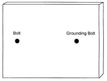
- Pierce two holes near the ends of the lid. Enlarge the holes with a pen or pencil until the bolts would fit through. Mount the bolts on the outside about half way through the holes so there is a washer and nut holding it in place on both sides. Tighten. Label one hole “grounding bolt” on the inside and outside.
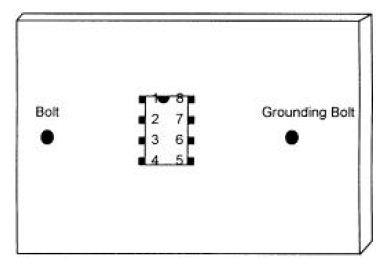
- Mount the 555 chip in the wire wrap socket. Find the “top end” of the chip by searching the outside surface carefully for a cookie-shaped bite or hole taken out of it. Align the chip with the socket and very gently squeeze the pins of the chip into the socket until they click in place.
- Make 8 pinholes to fit the wire wrap socket. Enlarge them slightly with a sharp pencil. Mount it on the outside. Write in the numbers of the pins (connections) on both the outside and inside, starting with number one to the left of the “cookie bite” as seen from outside. After number 4, cross over to number 5 and continue. Number 8 will be across from number 1.
- Pierce two holes ½ inch apart very near to pins 5, 6, 7, and 8. They should be less than 1/8 inch
away. (Or, one end of each component can share a hole with the 555 chip.) Mount the .01 uF capacitor near pin 5
on the outside. On the inside connect pin 5 to one end of this capacitor by simply twisting them together. Loop the capacitor wire around the pin first; then twist with the long-nose pliers until you have made a tight connection. Bend the other wire from the capacitor flat against the inside of the shoe box lid. Label it .01 on the outside and inside. Mount the .0047 uF capacitor near pin 6. On the inside twist the capacitor wire around the pin. Flatten the wire from the other end and label it .0047. Mount the 3.9 KW resistor near pin 7, connecting it on the inside to the pin. Flatten the wire on the other end and label it 3.9. Mount the 1 KW resistor and connect it similarly to pin 8 and label it 1K.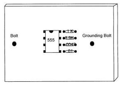
- Pierce two holes ½ inch apart next to pin 3 (again, you can share the hole for pin 3 if you wish), in the direction of the bolt. Mount the other 1 KW resistor and label inside and outside. Twist the connections together and flatten the remaining wire. This resistor protects the circuit if you should accidentally short the terminals. Mount the 3.9KW resistor downward. One end can go in the same hole as the 1K resistor near pin 3. Twist that end around pin 3 which already has the 1K resistor attached to it. Flatten the far end. Label.
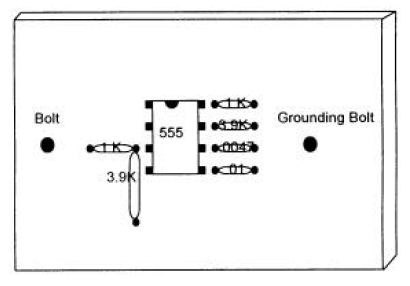
- Next to the 3.9KW resistor pierce two holes ¼ inch apart for the LED. Notice that the LED has a positive and negative connection. The longer wire is the anode (positive). Mount the LED on the outside and bend back the wires, labeling them + and – on the inside.
- Near the top pierce a hole for the toggle switch. Enlarge it until the shaft fits through from the inside.
Remove nut and washer from switch before mounting. You may need to trim away some paper with a serrated knife before replacing washer and nut on the outside. Tighten.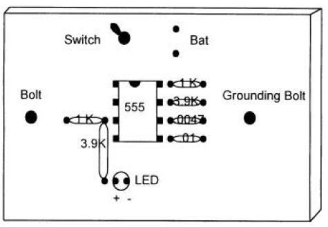
- Next to the switch pierce two holes for the wires from the battery holder and poke them through. Attach the battery and tape it to the outside.

NOW TO CONNECT EVERYTHING
First, make holes at the corners of the lid with a pencil. Slit each corner to the hole. They will accommodate extra loops of wire that you get from using the clip leads to make connections. After each connection gently tuck away the excess wire.
- Twist the free ends of the two capacitors (.01 and .0047) together. Connect this to the grounding bolt using an alligator clip.
- Bend the top ends of pin 2 and pin 6 (which already has a connection) inward towards each other in an L shape. Catch them both with an alligator clip and attach the other end of the alligator clip to the free end of the 3.9KW resistor by pin 7.
- Using an alligator clip connect pin 7 to the free end of the 1KW resistor attached to pin 8.
- Using two microclips connect pin 8 to one end of the switch, and pin 4 to the same end of the switch. (Put one hook inside the hole and the other hook around the whole connection. Check to make sure they are securely connected.)
- Use an alligator clip to connect the free end of the other 1KW resistor (by pin 3) to the bolt.
- Twist the free end of the 3.9KW resistor around the plus end of the LED. Connect the minus end of the LED to the grounding bolt using an alligator clip.
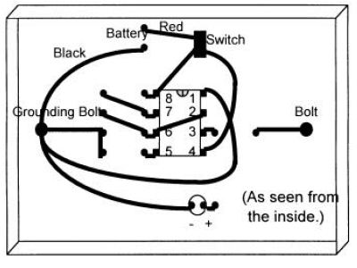
- Connect pin number 1 on the chip to the grounding bolt with an alligator clip.
- Attach an alligator clip to the outside of one of the bolts. Attach the other end to a handhold (copper pipe). Do the same for the other bolt and handhold.
- Connect the minus end of the battery (black wire) to the grounding bolt with an alligator clip.
- Connect the plus end of the battery (red wire) to the free end of the switch using a microclip lead. If the LED lights up you know the switch is ON. If it does not, flip the switch and see if the LED lights. Label the switch clearly. If you cannot get the LED to light in either switch position, you must double-check all of your connections, and make sure you have a fresh battery.
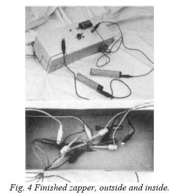
- Finally replace the lid on the box, loosely, and slip a couple of rubber bands around the box to keep it securely shut.
- Optional: measure the frequency of your zapper by connecting an oscilloscope or frequency counter to the handholds. Any electronics shop can do this. It should read between 20 and 40 kHz.
- Optional: measure the voltage output by connecting it to an oscilloscope. It should be about 8 to 9 volts. Note: a voltage meter will only read 4 to 5 volts.
- Optional: measure the current that flows through you when you are getting zapped. You will need a 1 KW resistor and oscilloscope. Connect the grounding bolt on the zapper to one end of the resistor. Connect the other end of the resistor to a handhold. (Adding this resistor to the circuit decreases the current slightly, but not significantly.)
The other handhold is attached to the other bolt. Connect the scope ground wire to one end of the resistor. Connect the scope probe to the other end of the resistor. Turn the zapper ON and grasp the handholds. Read the voltage on the scope. It will read about 3.5 volts. Calculate current by dividing voltage by resistance. 3.5 volts divided by 1 KW is 3.5 ma (milliamperes).
Using The Zapper
- Wrap handholds in one layer of wet paper towel before using. Grasp securely and turn the switch on to zap.
- Zap for 7 minutes, let go of the handholds, turn off the zapper, and rest for 20 minutes. Then 7 minutes on, 20 minutes rest, and a final 7 minutes on.
Trying the zapper on an illness to see “if it works” is not useful. Your symptoms may be due to a non-parasite. Or you may reinfect within hours of zapping. The best way to test your device is to find a few invaders that you currently have (see Lesson Twelve, page 492, or Lesson Twenty Seven, page 509). This gives you a starting point. Then zap yourself. After the triple zapping, none of these invaders should be present.